Wednesday, February 5, 2014

Tweet, tweet!

I've relied heavily upon SSH to program and monitor the weather station, but that isn't a very elegant solution and isn't visible to anyone else. Moreover, I can't monitor the station (or even see the data) when I'm away from my home network.

I considered setting up a static IP address for the Pi and essentially having it act like a server, but I was afraid that the extra network traffic (both intended and unintended) could hamper the Pi's performance. I also thought of building a website where the Pi could send its data and then be viewed by anyone online, but I didn't want to pay for the domain, hosting services, etc. For now, I'd just rather have some 3rd party website manage and disseminate my data. That's where Twitter comes in.

I found Twython, which is a Python library for managing a Twitter account. It allows you to post text, pictures, and videos and probably do a bunch of other things that I didn't take time to learn about since I will be just posting text (maybe a webcam later though...).  I signed up for a new Twitter account so that I don't spam my current followers.  Twython requires you to set up a new Twitter application at dev.twitter.com and record the consumer and access keys in your script.  There is a good tutorial HERE. After that, you can compose a Tweet with a single Python command.

The tweet.py script that I wrote ingests the current conditions from current.txt and outputs them (nicely formatted) to Twitter.  It serve a few other functions like converting to Fahrenheit, calculating relative humidity, converting to sea-level pressure, and converting wind speeds from rpm to mph.  The script is run every 10 minutes with Cron.
Here's the output. "The View" is the name of my apartment complex. 
Note that the account has a new handle since this screenshot was taken.

Right now it just prints the one-minute average every 10 minutes, so Twitter is essentially ignoring 9 minutes worth of data. I might work to fix this and add 10-minute or 5-minute averages, but it works just fine for me for now.  

For those of you who are interested, my handle is @viewwx (click link for my profile).  I don't regularly check it, so it is still better to contact me via my personal account @aaronmangels.

Station setup

It isn't an ideal situation since I live in an apartment and don't have a nice open place to setup the station. Anyway I decided to test the reliability of the station by setting it up on our balcony.  The wind measurements are obviously incorrect since the building blocks most of the wind, but temperature, humidity, and pressure should be reasonably accurate (at least locally).  The windvane and anemometer move occasionally with wind gusts, so it is still possible to see that they're working.  The wires run under our door so that the Pi can be housed indoors in order to protect it from the weather.
Balcony setup

Programming...

I've avoided blogging about programming until this point because its been a work in-progress.  I'm finally at a point where I'm happy with the code that is running and the output files.  Here is a brief rundown of the programs that run the weather station.

  • 4 Python scripts to query each sensor once per second (1Hz) and write the output to a temporary text file for later analysis
    • TempHumi.py (relies on rpiSht1x python library)
    • PresTemp.py (relies on Adafruit I2C libraries)
    • wdir.py (relies on Adafruit software-level SPI implementation)
    • wspd.py (uses RPi.GPIO to interrupt and count each pulse)
  • A Fortran (used because of speed and familiarity) program to analyze each of the temporary text files every minute
    • Finds average temperature, dewpoint, pressure, and windspped
    • Finds the maximum 3-second wind gust
    • Uses the Yamartino Method  to calculate average wind direction and standard deviation
    • Generates summary each minute and writes it into the appropriate text file for the day/month/year
    • Generates current.txt which will be used for future projects (updating websites, Twitter, etc.)
  • A scheduling python script to call the Fortran program at XX:XX:00 (better sleep functions than Fortran
  • Cron tasks to call each of the Python scripts at reboot

Interfacing with Raspberry Pi

Up until this point, I had just been using a breadboard to connect the Pi to the sensors so it was time to make something more permanent in the form of an add-on shield.  

I started with a piece of protoboard and some screw terminals from RadioShack and a GPIO header extension from Adafruit.  The analog-digital converter (to read the potentiometer) needs to be incorporated into the board and each of the screw terminals needs to connect to the corresponding GPIO pins.  I'm not terribly confident with my soldering skills, but I decided to give it a shot.  To my surprise, it worked on the first try!
Bottom side of the board

Since the Raspberry Pi doesn't have a real-time clock, I decided to add one onto the shield.  Adafruit has a couple RTCs to choose from, and I chose the cheaper of the two for $9.  See DS1307 HERE.  It easily interfaces via I2C and will keep time when detached from the network and even when powered off.  This one might lose/gain up to 2 seconds per day, but that isn't a huge concern since it can periodically get the time over the Internet.  

Top side of the board plugged into the Pi. 
Real Time Clock is the blue board on the bottom right

Putting It All Together!

Now that all the pieces were complete, I could go about building the support structure for the sensors.  I'll admit that it is rather simple and crude at this point, but it works!

I basically just made a "T" with two old chunks of 2x4, and added some u-bolts to the vertical board so that I can attach it to a fencepost, railing, or elsewhere.  To add rigidity and allow for easier removal, I added a piece of 1x4 to the bottom of the windvane and anemometer and a piece of steel to the top of the radiation shield.  In order to protect the sensitive electronics, I did my best to seal all holes and leaks with silicone adhesive.  
\
The (almost) finished project. Yes, I know that the wires and duct tape are messy...

Tuesday, February 4, 2014

Anemometer (and calibration)

The last component of the station is the anemometer.  Rather than trying to build a set of anemometer cups (that probably wouldn't be very accurate) I chose to buy a set of Davis cups from eBay (~$15).  I looked at 3D printing the necessary parts, but 3D printing services are too expensive and I don't have my own 3D printer (yet...).  The rest of the setup was relatively easy to put together.
These are similar to the cups that I used

I used 1/8" rod and another old Tupperware container with two ball bearings to allow the shaft to rotate freely.  I actually had to sand down the shaft for it to fit in the bearings.  In order to keep the shaft from sliding out, I didn't sand the ends of the shaft so that the shaft is essentially press-fitted into the bearings.  I glued the magnet onto the shaft vertically and placed the hall sensor next to it on a  piece of perfboard.  The magnet causes the sensor to fall LOW each time it spins, and the Raspberry Pi can easily count each of these pulses.

Its easy to calculate the speed of the anemometer in rotations per unit time, but that is relatively meaningless and there is no way to simply convert from rpm to mph (or kph, kts, m/s, etc.) -- there are simply too many variables (cup size, anemometer weight, friction, etc).  I need to correlate my anemometers rpm with known wind speeds.  I decided the best way to do this and get a good range of wind speeds would be with my car.

I chose a mostly calm day to do the calibration so that ambient winds wouldn't harm my readings.  I wrote a simple python script to log the number of pulses that the anemometer produced.  I plugged the Raspberry Pi into my cigarette lighter and SSH'd into my Pi with my computer to control it.  To further complicate things, I had to create a mobile hotspot on my phone in order to stay connected away from my house.  Luckily, my girlfriend was happy to help out since I don't have enough hands to drive, control the Pi, and hold the sensor at the same time.  I drove and held the sensor out of the window while she ran the python script.  We collected data from 5 mph, 10 mph, 15 mph, etc up to 50 mph.

When we got back, I plotted and graphed the data in Excel and was surprised to find that the relationship was very linear.  The linear regression equation came out to be y = 1.9757x + 0.2395, where x is in rotations/second.  The R-squared statistic was good considering the crude calibration method at 0.9976.  

See the finished pictures to see the anemometer. 

Wind Vane

Next up is the wind vane.  

Although wind vanes are easy to find and relatively inexpensive, I once again decided to make my own rather than just purchase one.  I thought this would be a relatively easy step, but it actually proved to be somewhat tricky.

My primary concern was that the potentiometer requires a non-negligible amount of torque to spin; therefore, my wind vane would need to be larger to allow even small breezes to turn the shaft.  I decided to use a scrap sheet of stainless steel to cut out a standard wing shape, but I found that the end result was very unbalanced and wouldn't rotate smoothly.  To compensate for this, I cut a chunk of 1" steel rod and soldered it to the front edge of the vane.  This moved the center of mass forward far enough that it wouldn't be biased even if the platform isn't completely level.  

I attached the vane to a piece of 1/8" rod and glued it inside of a small plastic tube that fit around the potentiometer shaft perfectly.  I housed the entire assembly inside of an old Tupperware container and added a bearing to the top to allow smoother motion.  

The vane works and reacts to relatively low (~5 MPH) breezes, but it isn't very visibly appealing (see it in the pictures of the finished station in a later post).  I will likely replace it with a vane from Davis (~$15) in the future. 
One of these will make the station look a little more professional

Solar Radiation Shield

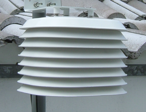
The thermometer/hygrometer need an enclosure to shield them from direct solar radiation that would otherwise skew the results during the daytime.  This shield has to allow for adequate ventilation so that the measurements are representative of the ambient air conditions, but it also needs to keep the sensors dry and protected from the elements.  Most of these shields rely on some wind for ventilation, but some (ASOS sites especially) use fans to force air across the sensors at a constant rate.  I decided that natural aspiration was good enough for now, and would keep power requirements low.
Typical naturally aspirated shield

Several companies sell products like this, but they are surprisingly expensive for something so simple. Keeping with the DIY nature of the project, I decided to make my own.  I decided that plastic bowls would be the perfect size and I found some relatively cheap at Walmart.  From there, I used a holesaw to cut 1.5" holes in the center of two of the bowls and drilled three holes in the bottoms of each to connect them together.
The two middle bowls

Since the bowls are red, I decided it would be best to paint them white in order to reflect the most sunlight. Initially, I just used generic, cheap spraypaint, but it quickly flaked off of the bowls.  I ended up having to sand them down and use Krylon "Fusion" paint, and now they look fantastic.

To finish it up, I used three threaded rods and some bits of rubber hose to connect the bowls and offset them from one another.  I decided to stick the barometer in this enclosure as well so that I don't need to make a separate one (though I will be making a more robust barometer housing in the future).  I soldered the two sensor breakouts onto a piece of perfboard and glued the entire board into the enclosure.  The sensors use 4 GPIO pins in addition to 3.3v and ground, so I used two separate runs of 4-conductor phone line to connect to the Pi.


I'm Still Here!

Okay, I'll admit that I've neglected this blog for almost 6 months now, but I have still been working on the weather station.  I actually have made very significant progress, but I just haven't had time to document it. Now that I've graduated, I have a little more spare time, and I'll try to bring this blog up to date!

Wednesday, August 14, 2013

Testing with an LCD

While I was testing the different sensors on the breadboard, I put together a circuit with the BMP085 and the SHT11 and added an 16 x 2 character LCD.  I wrote code to update the screen every 2 seconds and loop between displaying data from the SHT11 and the BMP085.  It only displays the raw data from the sensors; there is no datalogging capability.  Here's the short video of it running.


As you can see, the LCD screen is using a bunch of wires. It actually uses 6 GPIO pins (and a lot of power...my cheaper phone chargers wouldn't keep up), so I probably won't be able to include it in the final version the way it is.  Adafruit does make an I2C LCD shield that would be more applicable for my project (actually this started out as an I2C shield but I goofed up the wiring and ruined the GPIO expander).  

This was just something fun for me and was a good way to show people what I'm actually trying to do.  

Bourns Potentiometer

To determine wind direction, I had been thinking of using some kind of potentiometer for some time, but none of them that I had seen could do a continuous 360 degree rotation.  Then I found a post on Instructables from msuzuki777 where he made a weather station using an Arduino (check it out here). In the instructions, he mentions the continuous-turn potentiometer that he used for wind direction. From this I ended up buying two different potentiometers from Digikey, but only one of them was accurate enough for wind measurement (the other, cheaper one had a huge deadband).  

This turned out to be the Bourns 6639S-1-103. It ended up having very little deadband and was fairly consistent on its measurements. The only issue is that the Raspberry Pi is a digital-only device and has no way to directly measure an analog input.  This is very easy to do on an Arduino, but you must use an analog-to-digital converter (ADC) on a Raspberry Pi.

Bournes Continuous-Rotation Potentiometer from Digikey

For the converter, I used the MCP3008 from Adafruit which was only a few dollars.  It is an 8-bit converter, meaning that it separates the analog voltage into 1024 steps which is plenty for a wind vane.  The ADC connects to the Raspberry Pi via SPI which is slightly more difficult to use than I2C, but Adafruit had great code written for the converter already.

MCP3008 ADC from Adafruit

The only thing left to do here is to get the whole setup attached to a wind vane. I will have to ensure that the wind vane is large enough to provide enough torque to turn the potentiometer at relatively low wind speeds.

Hall Effect Sensor

For wind speed, I decided to build my own anemometer rather than just buy one off of the shelf.  I figured I could do a satisfactory job for significantly less money than most digital anemometers cost. Basically I need to determine how many times the rotor spins in a given period of time, and then I can correlate that to a wind speed (in mph, kph, knots, m/s, etc...). 

To accomplish this, I need a momentary switch of some kind to send an interrupt signal over a GPIO pin to the Pi, but I didn't want to introduce any extra drag into the system. In this situation, a reed switch or hall-effect switch would be perfect. Both of these sensors detect the presence of a magnetic field.  I found that Adafruit had a hall-effect sensor that they had tested, and I determined that it would be perfect for my setup.  
Hall-effect sensor from Adafruit. And yeah, that's a quarter next to it... This thing is tiny!

I also acquired a neodymium magnet and tested the sensor. Adafruit came through again. This sensor was great!  There were literally no issues with bounce which should make coding easier (read more about bounce). It only requires you to connect power, ground, 1 GPIO pin, and a pullup resistor. Now it is time to integrate this thing with a set of wind cups and get it calibrated.  

Sensirion SHT11

As it turns out, it is much more difficult to find an acceptable, low-cost humidity sensor.  I tried several sensors including the DHT11, DHT22, and AM2302 before deciding that none of them would work well. They weren't particularly accurate and they were extremely difficult to interface with. Eventually I broke down and decided to spend a little more on a better sensor.  The SHT line of sensors from Sensirion turned out to be fantastic. They are very accurate for both temperature and humidity (especially the higher-end ones), and with the help of a Python package that I found online (rpiSht1x - read more here), they are pretty easy to interface with via 2 GPIO pins.

SHT11 Breakout Board from Adafruit

I currently have the SHT11 which is the mid-level sensor that Sensirion offers.  I would like to upgrade to the SHT15 but it is more expensive and difficult to find as a breakout board.  If I can find it, I would like to buy the SHT75 which has leads attached to it from the factory.  Another option is to switch over to Sensirion's newer SHT2x series that communicates to the Pi via I2C (see Sensiron's lineup of humidity sensors at their website).  These other sensors would be great in the future, but the one I have will work just fine for now. 

Bosch BMP085

The BMP085 was actually the first sensor I bought.  It is quite accurate with resolution down to 0.03 hPa.  It is also very affordable.  The chip itself is available for about $5 but since I have no way to solder surface-mount devices (SMT), I had to buy breakout boards that were slightly more expensive. Lastly, the BMP085 is easy to work with as it transmits data via I2C which is supported by the Raspberry Pi.  

BMP085 Breakout Board from Adafruit

Another (cheaper) Breakout Board from SainSmart

The documentation for the board was fantastic, especially from Adafruit.  Their tutorials were fantastic, and they actually have a whole library of code to get their sensors working on the Raspberry Pi.  For this reason, you will see that Adafruit became a go-to source for parts and documentation.

Sensors!

Over the course of the summer, I decided on and purchased the sensors that I will use for the basic meteorological observations (temperature, humidity, pressure, wind speed, and wind direction).  

The ones I decided on are:
1.) Bosch BMP085 - Pressure and Temperature
2.) Sensiron SHT11 - Humidity and Temperature
2.) Melexis Technologies Hall Effect Sensor - Wind Speed
4.) Bourns Inc. Potentiometer - Wind Direction

Basically, I tried to incorporate sensors that fulfilled three requirements.  These were affordability, accuracy, and ease of use.  I will go through each of the sensors individually in the posts to follow!

Update!

Its been over three months since my last blog post, but I assure you that this project is still alive and well!

In the meantime I've been volunteering at the National Weather Service in Hastings, NE, working at Midwest Independent Soil Samplers, and doing other fun, summer stuff.  Needless to say, this has kept me pretty busy, and I have hardly had time to work on the station (let alone blog about it).

Fortunately though, I have had some spare time now that the summer is winding down to dig in to my project.  My next several posts will update you with the things that I have accomplished on the station.  

Saturday, May 11, 2013

Goals!

Alright, so now its time to dig in to what I want to do with this project!

Basically, my ultimate goal is to affordably replicate the basic functionality of the official automated airport weather stations.  Doing this will allow me to have observational data for my exact location at a higher temporal resolution (airport sites typically only report a few times per hour at most; I would like to have 1-minute observations).  Furthermore, by developing a low-cost system, the station could be more easily adopted to provide better spatial resolution for surface observations, to create a mesonet, or even to build portable observation pods.

Here is some information on airport weather stations.  Most of the sites are designated as AWOS or ASOS.  These sites are run by the National Weather Service, the Federal Aviation Administration, and the Department of Defense.
ASOS Site

Here is a breakdown of the different parameters that I would like my station to measure (in order of importance):
  1. Temperature
  2. Barometric Pressure
  3. Humidity
  4. Wind Speed
  5. Wind Direction
  6. Precipitation
  7. Lightning
  8. Soil Temperature
  9. Soil Moisture
  10. Solar Radiation
  11. Photography (webcam or still-shots)
There are a few other considerations that I will try to work into my station:
  1. Battery power
  2. Solar power
  3. Real-time clock
  4. Portability
  5. Long-term data logging
  6. Data relay via internet
  7. Data relay via cellular connection
  8. Data relay via radio (APRS)

Who am I?

Okay, I'll keep this post short because you guys probably aren't too concerned with getting to know me, but I think having a little bit of background on what I know and where I'm from would be good.

I am studying meteorology at the University of Nebraska-Lincoln and I am in my senior year.  I have some programming experience, but I haven't done any extensive embedded systems programming. Therefore, I will be relying heavily on information and code from others and modifying it to serve my purpose.

Since I promised to keep this short, I won't add any more personal information.  If you want to know more, follow me on Twitter @aaronmangels, comment below, or send me a message.

Me with our new dog Cooper.

What is the Raspberry Pi and why did I use it?

I've never heard of Raspberry Pi...What is it?
For those of you who are unfamiliar with the Raspberry Pi, it is a credit card sized, Linux computer that was designed by the Raspberry Pi Foundation in the UK.  This nonprofit foundation designed it in an effort to get schoolchildren interested in computers and programming.  They initially released a batch of 10,000 "Model B"boards for $35 apiece, and they quickly (within an hour) sold out.  Since then, they have been able to maintain a steady supply of boards and have released a "Revision 2" and a cheaper "Model A" version for $25 (their original pricing goal).

Okay, Cool! So what can it do?
At the heart of the Raspberry Pi is a 700 mHz ARM11 processor.  The foundation describes it to be roughly equivalent to an old 300 mHz Pentium II processor, but with much better graphics.  Because of the Broadcom GPU that is included on the board, the Pi can decode 1080p video and is about graphically equivalent to the original Xbox.  Also, the Model B board includes 512 mb of RAM along with 2 USB ports, an ethernet port, HDMI and composite video ports, and a header of GPIO (General-Purpose Input/Output) pins.  (The Model A has 256 mb of RAM, 1 USB port, and no ethernet.)  

Why did you decide to use it?
Getting a full-featured computer at such a low price and small form factor just seemed too good to pass up, so I quickly snatched up on of the Model B Revision 1 boards.  I thought initially I could make a set-top box for media streaming/viewing, but the lack of Netflix support killed that idea.  I didn't do much with it for a few months, but then I realized that it would lend itself well to a homebuilt weather station.
The ARM11 processor is more than fast enough, and it consumes very little power (~2W) so I could possibly run it off of battery/solar power.  The GPIO pins allow me to interface directly with almost any sensor you can think of.  Essentially, the Pi is giving you most of the same interfaces as an Arduino for the same price, but the Pi is an complete computer while the Arduino isn't.  With such huge interest in the Pi, there is already a large and expanding user base to test and write code for the different sensors I will be using.  Most importantly, its cheap! So when I screw up, I don't have to break the bank to replace the system.

Raspberry Pi (Model A)
Here's a picture of my Model A that I just got.  (My Model B is busy at the moment)

If you want to learn more about the Raspberry Pi, visit the foundation's website at raspberrypi.org.  

First Post!

Hello, my name is Aaron Mangels and welcome to my (first ever) blog.  
If the title of my isn't obvious enough, I will be building a weather station based around the Raspberry Pi.  I already have been tinkering with it for several months, but now I'm finally able to devote enough time to the project to actually go somewhere with it (and blog the process). 
Thanks for reading, and hopefully you will find it useful and interesting!